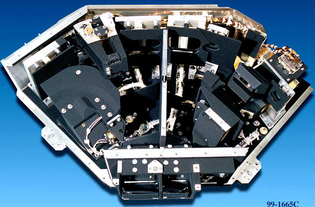
| If we take the mechanical layout shown in the instrument overview and put the optical rays on top, it is so confusing we can't figure out how it works ourselves. We will explain how the instrument is supposed to work with this simplified optical layout instead. (See figure to the right). | |
 |
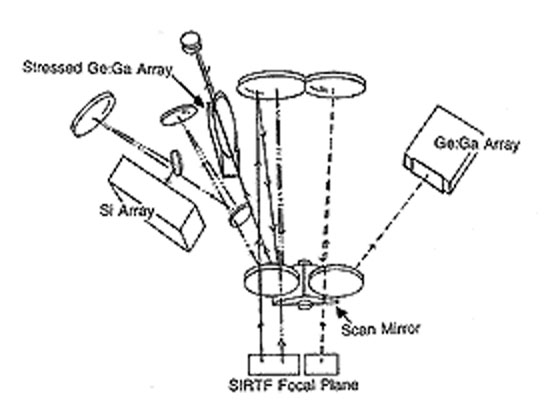 |
The optics are shown in the configuration for mapping. MIPS has two pickoff mirrors in the SIRTF focal plane. The one on the right in the figure feeds the 32x32 array for 70 microns. The light off the pickoff goes to a large mirror at the back of the instrument that forms a pupil on one facet of the scan mirror (near the front of the instrument). The facet is angled so the image is relayed directly to the detector array. The left side pickoff mirror feeds both the 128x128 24 micron array and the 2x20 160 micron one. As with the 70 micron channel, first the light goes to a large mirror at the back of the instrument, which in this case forms a pupil on the second facet of the scan mirror. The facet is angled to relay the beam to the left; however, where the focal plane is relayed, mirrors are used to divide it for the two channels. Additional relay mirrors reimage each piece of the focal plane onto the appropriate array.
When the scan mirror is tilted, the light can be fed into additional optical trains for the 32x32 array. One provides twice the magnification, so the pixels project to only 5 arcsec width on the sky. This mode gives a high degree of oversampling of the Airy disk to support superresolution. The other position feeds the light into the low resolution spectrometer optics. Neither of these trains is shown in the figure.
 |
|
|