Results
The plot of brightness vs DCE number is given below.
Principal:
Deputy:
Analyst:
AORKEYS:
Last Updated:
All of the 9 DCE exposures were run through mips_sloper. When we
have higher sky levels, we will also run the data through mips_caler
to stim-calibrate the darks. For this campaign, we used the program
plot_mcnts.pro to plot the mean array brightness vs DCE number with
no stim calibration. This program is part of the pipeline distribution.
A visual inspection of the data showed that the noise levels were
larger than the differences with scan mirror angle, so no further
analysis was performed.
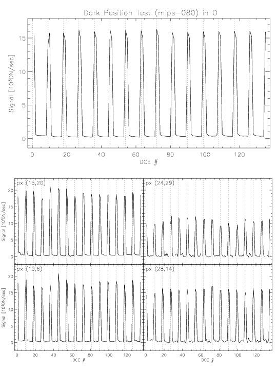
The plot of brightness vs DCE number is given below.
Results
This plot shows 15 sets of data, bracketed by stim flashes on either end. The first set was taken while pointing at the sky. It is only slightly brighter than the dark data itself. The next seven sets of darks were taken at the 70um primary dark position. The last seven sets of data were taken at the 70um secondary dark position. There is a noticeable difference in brightness between the primary and secondary dark positions, but for a given dark position, the scan mirror dependent differences are too small to see.
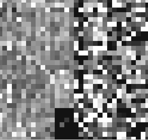
The following plot show a ratio of single DCEs from the first and last scan mirror positions at the primary dark position. If there were a significant scattered light component, the ratio would likely show some horizontal shading. The lack of any such features shows the insensitivity of the dark image on scan mirror position at these low sky levels.
The 70um primary dark position is significantly darker than the secondary dark position. However, this task will need to be repeated with SIRTF pointed at bright sky if we are to determine the best scan mirror pointing for the 70um primary dark position.
A preliminary comparison has been made of 70um and 160um dark
levels at the 70um primary dark position and the 160um dark position
(which puts the 70um array in SED mode). The differences in dark
levels are not obvious on either array. As a result, it is unlikely
that we will see much of a dependence of 70um dark levels on exact
pointing of the scan mirror, and we can probably use one pointing
for both 70um and 160um dark calibration -- either the 70um primary
dark position or the 160um dark position.
Output and Deliverable Products
None.
Actions Following Analysis
None.