Principal: Chad Engelbracht
Deputy: James Muzerolle, Jocelyn Keene, Bill Wheaton
Data Monkey(s): Myra Blaylock
Priority: Critical
Downlink Priority: Expedited
Analysis Time: 12 hours
Last Updated:
To determine if the 24µm array is responding to illumination through the telescope, and to verify that basic instrument properties (e.g. throughput, image quality, CSMM operation) are as expected.
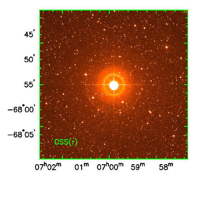
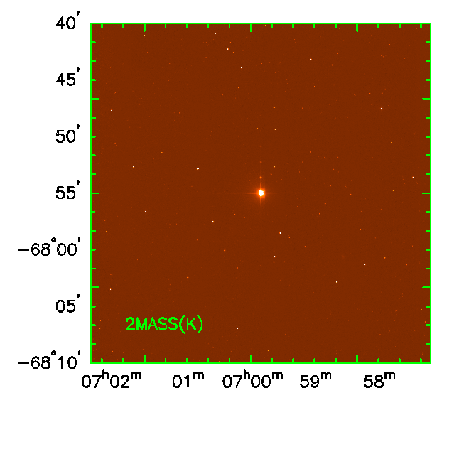
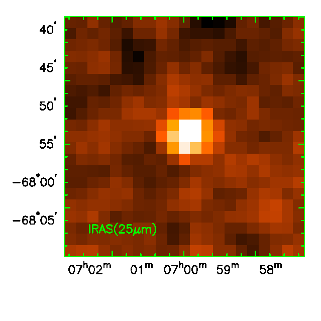
Place a bright MIPS flux standard in the 24µm FOV. Execute 2 cycles each of the 24µm photometry small-field and large-field AOT using 3s exposures. The large-field AOT should be executed with a sky offset small enough to keep the star on the array during the background observation. The target definition for the large-field observation should include an offset half the size and in the opposite sense of the background field offset. This will center the star in the large-field observations and maximize the chance that the star will be on the array in all exposures. The target should be one of our focus-check standards in the CVZ, e.g., the K3III HD 53501, which is about 1.2 Jy at 24µm. This star was chosen because:

|

|

|
The AOTs described will generate 74 DCEs on each array. The 24µm data are expected to look something like Figure 1, which shows simulated images of a 1 Jy point source against a moderate background that includes zodiacal light, background galaxies, and cirrus. Read noise, dark current, photon noise, and cosmic rays are included in the simulation.
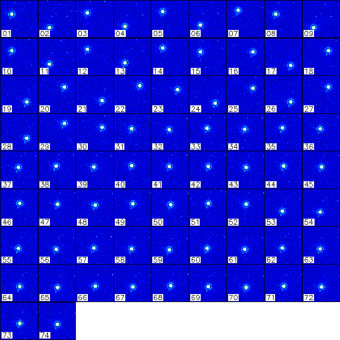
Figure 1: Simulated images of
24µm first-light data.
Array Data Desired:
24 µm
Data Reformatting Option:
Some checks of the data need to be performed quickly to
assess whether we'll need to delay campaign D2 due to the background being too
high. The results should be reported to the instrument P.I.
Some quick checks can be performed to verify that certain properties of the data are as expected:
These data will be the first sky observations obtained by MIPS that will not be saturated. Thus, there will not yet be a proper flat field to support standard pipeline operation. A usable dark will be obtained from the scattered background measurement made in the same campaign. The data will be processed with the SSC pipeline to subtract the dark and to perform linearity and droop corrections.
A simple flat field will be generated by median-combining the small-field data, as shown in Figure 2. The large-field data should be avoided because the concentration of source positions near the center of the array will bias the flat field. This can be done using IRAF's "imcombine" task or using mips_enhancer. The data can then be processed again, this time using the flat field generated from the data themselves.

Figure 2: Simulated flat-field image.
The data should be shifted and coadded into a mosaic. This will provide us with a higher S/N, better-sampled image of a point source that is free of cosmic ray effects. Mips_enhancer can be used to do this, but it requires accurate pointing information in the image headers. Should there be a problem with the headers, we'll need some way to get the correct information to mips_enhancer. This requires both a way of quickly computing centroids in a long list of images and a way to translate those centroids into appropriate pointing information for mips_enhancer. I have a perl script which generates a list of relative offsets from the log file produced by IRAF's "imexam" task which would serve this purpose. If we need to use IRAF's "imcombine" task as a backup for mips_enhancer, I have another perl script which will generate a list of offsets from the image WCS parameters. This script is not useful for mips_enhancer, of course, which can compute the pointing from the WCS parameters independently. Those familiar with IRAF's imcombine task will remind me that it can also compute offsets from WCS parameters, so this last script is really only useful if you want to get better sampling by using the "ircombine" task in the FSpec data reduction package. A mosaic of the data shown in Figure 1 can be seen in Figure 3, where the display range is the same as the flat field shown in Figure 2.
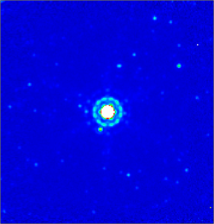
Figure 3: Mosaic of the data
shown in Figure 1.
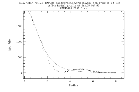
Figure 4: Radial plot of the 24µm PSF
generated by Tiny Tim.
We'll want to verify that the star is producing as many counts as expected. The current target chosen for this observation is a K3III star with an expected 24µm flux of about 1.2 Jy. Using a conversion factor of 1.4e5 (my estimate based on the instrument parameters) to 4.1e5 (estimated from the saturation limits on the SSC website) e-/s/Jy and a gain of 5 e-/DN, we expect a count rate of 34000 to 98000 DN/s (integrated over the PSF) from the star. We will use IDP3 and/or IRAF's "imexam" task to measure the total counts from the star.
We'll want to verify that the 3 different spacecraft offsets present in this sequence (small-field left to right offset, large-field left to right offset, large-field background offset) are correct. IDP3 will be used to compute centroids for the star before and after each offset, and the separations will be compared to the expected offset. The expected offsets are: 129" for the small-field offset, which occurs between DCEs 15 and 16; 11.5" for the large-field left to right offset, which occurs between DCEs 41 and 42 and again between DCEs 63 and 64; and 60" for the background offset, which occurs between DCEs 52 and 53.
We can quickly verify whether the CSMM positions are as expected throughout the sequence by consulting the image headers and comparing to the table below.
| DCE# | CSM_PRED |
| 1 | 1929 |
| 2 | 2150 |
| 3 | 1908 |
| 4 | 2128 |
| 5 | 1886 |
| 6 | 2106 |
| 7 | 1864 |
| 8 | 1929 |
| 9 | 2150 |
| 10 | 1908 |
| 11 | 2128 |
| 12 | 1886 |
| 13 | 2106 |
| 14 | 1864 |
| 15 | 1929 |
| 16 | 1929 |
| 17 | 2150 |
| 18 | 1908 |
| 19 | 2128 |
| 20 | 1886 |
| 21 | 2106 |
| 22 | 1864 |
| 23 | 1929 |
| 24 | 2150 |
| 25 | 1908 |
| 26 | 2128 |
| 27 | 1886 |
| 28 | 2106 |
| 29 | 1864 |
| 30 | 1929 |
| 31 | 2007 |
| 32 | 2022 |
| 33 | 2000 |
| 34 | 2014 |
| 35 | 1993 |
| 36 | 2007 |
| 37 | 2022 |
| 38 | 2000 |
| 39 | 2014 |
| 40 | 1993 |
| 41 | 2007 |
| 42 | 2007 |
| 43 | 2022 |
| 44 | 2000 |
| 45 | 2014 |
| 46 | 1993 |
| 47 | 2007 |
| 48 | 2022 |
| 49 | 2000 |
| 50 | 2014 |
| 51 | 1993 |
| 52 | 2007 |
| 53 | 2007 |
| 54 | 2022 |
| 55 | 2000 |
| 56 | 2014 |
| 57 | 1993 |
| 58 | 2007 |
| 59 | 2022 |
| 60 | 2000 |
| 61 | 2014 |
| 62 | 1993 |
| 63 | 2007 |
| 64 | 2007 |
| 65 | 2022 |
| 66 | 2000 |
| 67 | 2014 |
| 68 | 1993 |
| 69 | 2007 |
| 70 | 2022 |
| 71 | 2000 |
| 72 | 2014 |
| 73 | 1993 |
| 74 | 2007 |
The CSMM telemetry used to predict these values can be found in the keywords CSM_PIDX (POSINDEX), CSM_MOD (SCANMODE), ANCSMDIR (RAMPDIR), ANCSMPS2 (SCANPOS2), ANCSMRP1 (RELPOS1), ANCSMRP2 (RELPOS2), ANCSMSTP (STEPOFFSET), CSM_SLP (RAMPSLOPE), and DCE_CALC (STIMCYCLE). The expected values for the various modes can be found on the MIPS CSMM Configuration page.