70µm WF Focal Plane Survey, Fine

Principal: Jocelyn Keene
Deputy: Jane Morrison, Bill Wheaton
Data Monkey(s): Jane Morrison and Bill Wheaton
Priority: Critical
Downlink Priority: Normal
Analysis Time: Campaign Q: 2880 minutes, Campaign R: 2880 minutes, combining campaign Q and R: 120 minutes
Last Updated:


Objective

To measure the pixel locations (i.e. array orientation, scale,and distortion) as a function of scan mirror angle for the 70 µm wide field array configuration to an accuracy of 1.1 arcseconds relative to the PCRS.

Description

Use an IER based on the 70 µm photometry compact source AOT to measure the locations on the sky of several positions on the array as a function of scanning mirror angle.
This task is run in campaigns Q and R. The data from each campaign is processed separately by the MIPS and IPF teams. The IPF team then combines the results from both campaigns. The results from the IPF multi-run are used to update Frame Table 14. The frame table updates for all the campaigns can be found in the following table:
Frame Table Updates.

Data Collected

The observing strategy is exactly the same as 70 µm coarse, except that the set of observations is repeated for a total of 924 ( 462*2) observations. The IER is set up so data is collected in 3 columns on the array: on the left-side, center and right-side of the array. After moving the telescope in the V direction according to the V offset, the observational patter is repeated 7 more times (with a V offset between each set). The entire process is then repeated a second time.

Calibration Star

For the selected calibration star see the IER for this survey. The requirements on the 70 µm fine focal plane calibration star are as follows:

  • In CVZ
  • Mips requirements: stellar brightness corresponding to S/N of 30 (3 sec integrations) 0.212 Jy, K mag 1.25

    Observing Strategy


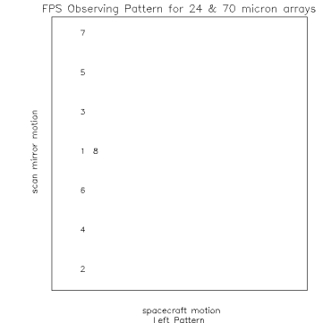
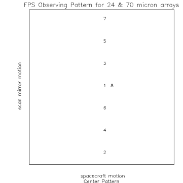
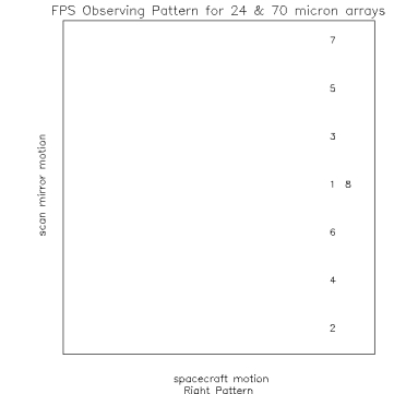
    Figure 1. Observing Pattern at 3 locations on the detector. Note size of box is not the total size of the array but a portion of the central region which depends on array and if it is a coarse or fine survey

    Definitions:

  • W axis direction is defined by the Frame Table, and is always within +/- 90 degrees of the TPF z axis as projected on the sky. Motion along this axis corresponds to motion in the spacecraft motion (left/right).
  • V axis direction is defined by the Frame Table, and is always within +/- 90 degrees of the TPF y axis as projected on the sky. Motion along this axis correspond to motion in the scan mirror direction (up/down).
  • W offset, the amount of motion in the W direction which results in the spacing between left array, middle array and right array observations
  • V offset, the amount of motion in the V direction which occurs between a set of observations.

    70 µm Coarse FPS observational parameters:

  • W offset = 120 arc seconds
  • V offset = 60 arc seconds
  • W dither = 15 arc seconds
  • V dither = 15 arc seconds
  • mirror locations for 1 position shown in figure 1.
    1. position 1 = 0
    2. position 2 = -60
    3. position 3 = 20
    4. position 4 = -40
    5. position 5 = 40
    6. position 6 = -20
    7. position 7 = 65
    8. position 8 = position 1 = 0

    Observational Strategy

  • Step 1
    1. PCRS observation
  • Step 2 - (total of 11 observations)
    1. Position the telescope so the data falls on the left side of array
    2. Position star at position 1 in figure 1 (left), turn stim on take an observation
    3. Turn stim off
    4. Take 8 DCES at positions shown in figure 1 (left)
    5. Position star at position 1, turn stim on and take observation
    6. With star still at position 1 turn stim off and take observation
    7. dither in V and W
    8. Repeat above 11 observations.
  • Step 3
    1. Move the space craft according to the W offset (120 arc seconds), image should now be on the center of the array.
    2. Position star at position 1 in figure 1 (middle), turn stim on take an observation
    3. Turn stim off
    4. Take 8 DCES at positions shown in figure 1 (middle)
    5. Position star at position 1, turn stim on and take observation
    6. With star still at position 1 turn stim off and take observation
    7. dither in V and W
    8. Repeat above 11 observations.
  • Step 4
    1. Move the space craft according to the W offset (138 arc seconds), image should now be on the right side of the array.
    2. Position star at position 1 in figure 1 (right), turn stim on take an observation
    3. Turn stim off
    4. Take 8 DCES at positions shown in figure 1 (right)
    5. Position star at position 1, turn stim on and take observation
    6. With star still at position 1 turn stim off and take observation
    7. dither in V and W
    8. Repeat above 11 observations in step.
  • Step 5
    1. PCRS observation
  • Step 6: move telescope according to V offset (60 arc seconds) and repeat steps 1-5
  • Step 7: move telescope according to V offset (60 arc seconds) and repeat steps 1-5
  • Step 8: move telescope according to V offset (60 arc seconds) and repeat steps 1-5
  • Step 8: move telescope according to V offset (60 arc seconds) and repeat steps 1-5
  • Step 9: move telescope according to V offset (60 arc seconds) and repeat steps 1-5
  • Step 10: move telescope according to V offset (60 arc seconds) and repeat steps 1-5
  • Step 11: Repeat Steps 1-10 a second time.

    Number of observations from step 1-5, 66. Step 1-5 repeated 7 times for a total of (66 * 7) = 462 observations. Repeat entire set for a total of 924 observations


    Data Reformatting Requirements

    Array Data Desired:

    70 µm Wide

    Data Reformatting Option:


    Task Dependencies


    Calibration Dependencies