There is a problem w/ your write-up. Check that you have valied entries
for \$CAID and \$Campn in your analysis.php file. If that checks out, then
Contact Stansberry";
return ;
}
// get first matching task
$row = mysql_fetch_array($result);
$title = $row["title"];
$princ = $row["principal"];
$deputy= $row["deputy"];
$campn0 = $row["campn0"];
$aorkeys = $row["aorkeys"];
// get real name of principal, deputies
$princ = ioc_get_person($princ);
$princ = $princ[0];
$deps = explode(",",$deputy);
foreach ($deps as $depty) {
$depty = trim($depty);
$depty = ioc_get_person($depty);
$depty = $depty[0];
$depty = explode(",",$depty);
$depty = $depty[0]; // last names only
$deplist[] = $depty;
}
$deplist = implode(", ", $deplist);
$caid = sprintf("%03d",$caid);
$file = "mips-".$caid.$campn.".analysis.php";
// if more matches, append the AORKEYS from those
$numrows = mysql_num_rows($result);
if ($numrows > 1) {
$aorkeys = " " . $numrows . " Task Executions: ". $aorkeys;
for ($i=0;$i < mysql_num_rows($result); $i++) {
$row = mysql_fetch_array($result);
$morekeys = $row["aorkeys"];
$aorkeys = $aorkeys .'; '.$morekeys;
}
}
// END PHP.
?>
<? echo "MIPS-$caid, Campaign $campn IOC/SV Analysis"; ?>
Principal:
Deputy:
Analyst:
AORKEYS:
Last Updated:
Task Outcome Summary
- DATA STATUS: Anomalous
- TASK OUTCOME: Anomalous
Abstract
The goal of MIPS-326 was to demonstrate the basic functionality of
the MIPS scan map AOT in its (most challenging) fast scan mode. The
task was remarkably successful for the most part, showing that the
CSMM could be used to obtain "freeze-frame" images in all three bands
with only a modest trailing of the images. The image blurring is
overwhelmingly in the scan direction and can be solved by a simple
change in the spacecraft scan rate. However, the data showed
an unexpected cross-scan offset of the first scan leg. This
offset is due to a problem in the AOT logic which is being addressed
by frame table changes.
Analysis
The design of the MIPS fast scan AOT is described in the SIRTF Observer's
Manual v3.0. The telescope points at the target, then uses PCS_SET_VW to
offset to the starting point of the map. For the purposes of this task,
we performed two one-degree-long scan legs with no cross-scan offset. The
scanning speed was "fast", equivalent to a telescope slew rate of
16840 milliarcsec/sec. During this AOT, the telescope scans a distance
of 4 160um pixels between mirror flybacks, forming a sparse map. The
forward scan leads with the 70um array (frame MIPS_70um_center).
Figure 1 depicts a visualization of the AOR used in MIPS-326.
Figure 1: Pre-launch SPOT visualization of section of
MIPS 326 scan map (on DSS)
After
several false starts in testing, we defined the CESCANCON parameter
RAMPDIR = 0 for forward scan and RAMPDIR = 1 for reverse scan. Unlike
the initial design, the PCS_SCAN_LEG RAMPDIR parameter is backward
from the CSMM parameter value (i.e. RAMPDIR=1 for forward scan
and RAMPDIR=0 for reverse scan). For forward scan, the other
CESCANCON CSMM parameters are SCANPOS2=0 (= SCANPOS1 = 2007),
RELPOS1 = 2048, RELPOS2 = 2048, RAMPSLOPE = 33, and STEPOFFSET = -29.
For reverse scan, these parameters are SCANPOS2 = 0, RELPOS1 = 2048,
RELPOS2 = 2048, RAMPSLOPE = 33, and STEPOFFSET = -29. It is vital
that RAMPDIR and STEPOFFSET be applied to the appropriate scan
direction. Otherwise, no image motion compensation is performed.
The data were collected on October 13 in Campaign H. The 24um data
were reduced using DAT v2.31, and the Ge data were reduced using
v2.32. The perl script of Chad Engelbracht was utilized to predict
CSMM DAC positions for each scan leg. These were compared versus
the CSMM_PRED keyword populated by the SSC pointing pipeline.
The predicted CSMM positions of each DCE is listed below in Table 1.
#DCEs
from Stimflash
|
Scan
Direction
|
CSM_PRED
|
0
|
FWD
|
2003.375
|
1
|
FWD |
1999.750
|
2
|
FWD
|
1996.125
|
3
|
FWD
|
1992.500
|
4
|
FWD
|
1988.875
|
5
|
FWD
|
1985.25
|
6
|
FWD
|
1981.625
|
7
|
FWD
|
1978.0
|
8
|
FWD
|
1974.375
|
9
|
FWD
|
1970.75
|
10
|
FWD
|
1967.125
|
11
|
FWD
|
1963.5
|
12
|
FWD
|
1959.875
|
13
|
FWD
|
1956.25
|
14
|
FWD
|
1952.625
|
15
|
FWD
|
1949.0
|
16
|
FWD
|
1945.375
|
17
|
FWD
|
1941.75
|
18
|
FWD
|
1938.125
|
19
|
FWD
|
1934.5
|
20
|
FWD
|
1930.875
|
21
|
FWD
|
1927.25
|
22
|
FWD
|
1923.625
|
23
|
FWD
|
1920.0
|
24
|
FWD
|
1916.375
|
25
|
FWD
|
1912.75
|
26
|
FWD
|
1909.125
|
27
|
FWD
|
1905.5
|
28
|
FWD
|
1901.875
|
29
|
FWD
|
1898.25
|
30
|
FWD
|
1894.625
|
31
|
FWD
|
1891.0
|
32
|
FWD
|
1887.375
|
33
|
FWD
|
2003.375
|
0
|
REV
|
2010.625
|
1
|
REV
|
2014.25
|
2
|
REV
|
2017.875
|
3
|
REV
|
2021.5
|
4
|
REV
|
2025.125
|
5
|
REV
|
2028.75
|
6
|
REV
|
2032.375
|
7
|
REV
|
2036.0
|
8
|
REV
|
2039.625
|
9
|
REV
|
2043.25
|
10
|
REV
|
2046.875
|
11
|
REV
|
2050.5
|
12
|
REV
|
2054.125
|
13
|
REV
|
2057.75
|
14
|
REV
|
2061.375
|
15
|
REV
|
2065.0
|
16
|
REV
|
2068.625
|
17
|
REV
|
2072.25
|
18
|
REV
|
2075.875
|
19
|
REV
|
2079.5
|
20
|
REV
|
2083.125
|
21
|
REV
|
2086.75
|
22
|
REV
|
2090.375
|
23
|
REV
|
2094.0
|
24
|
REV
|
2097.625
|
25
|
REV
|
2101.25
|
26
|
REV
|
2104.875
|
27
|
REV
|
2108.5
|
28
|
REV
|
2112.125
|
29
|
REV
|
2115.75
|
30
|
REV
|
2119.375
|
31
|
REV
|
2123.0
|
32
|
REV
|
2126.625
|
33
|
REV
|
2010.625
|
PSF in-scan and cross-scan FWHMs were measured for 24um using
IDP3. Astrometry versus IRAS point sources and 2MASS members
of M47 cluster stars was performed with IRAF.
Results
An initial quick look at the 24um data showed that the scan map mode works
roughly as designed, with individual sources seen in 5 - 6 consecutive
DCEs before disappearing off the array. Following the motion of
individual bright PSFs between DCEs, we find that the object moves
approximately 23 - 24 pixels. Presuming a Y image scale of 2.5981 arcsec
per pixel (J. Keene, private communication), this amounts to a motion of
about 62 arcsec between DCEs. This value agrees with the input scan
rate of 16.84 arcsec/sec and a time between DCEs of 3.5 MIPS seconds.
Individual PSFs are noticably blurred in the direction of scan mirror
travel. Figure 2 depicts a bright PSF from one of the IRAS point
sources imaged during the task.

Figure 2: PSF from an individual fast scan DCE. Slight vertical
elongation due to mismatch between the telescope slewrate and
the CSMM motion.
Using the IDL program IDP3, I fit two
dimensional gaussian models to PSFs at several positions across the
array. The following dimensions were determined: FWHM(y axis) =
3.197 +/- 0.1 pixels; FWHM(x axis) = 2.12 +/- 0.07 pixels. The cross-scan
PSF dimensions are close to identical to those derived for PSFs
taken in 24um small field photometry mode (MIPS 121E report) which
are 2.06 pixels FWHM in x. This demonstrates that the direction of
spacecraft motion is nicely aligned with the direction of scan
mirror travel. The elongation of the image in the scan direction
provides evidence that the CSMM and spacecraft rates are not
precisely matched. The degree of rate mismatch was determined by
taking the difference in x and y FWHM in quadrature, multiplying
by the y axis pixel scale, and dividing by the exposure time
of 2.62 seconds. I derive an adjustment of 2330 milliarcseconds/sec
from the current rate of 16840 milliarcsec/sec, a change of 14%.
Examination of the SUR image does not provide the sign of this
adjustment. However, comparison of the SUR and first difference
image suggests that the SUR PSF is extended in the direction
of CSMM travel, not spacecraft motion (thanks to J. Stansberry
for this suggestion). We will try both signs of the correction
in an experiment in Campaign K.
Mosaics have been created for the 24um data in the scan map using
the pointing reconstructions of the SSC to align the images. Both
MIPS Enhancer and MOPEX produce 24um images which are significantly
more elongated than the individual PSFs (see Figure 3).
Figure 3: Bright PSF from MIPS Enhancer mosaic of 24um scan map. Elongation is due to both CSMM/scanrate mismatch and WCS pointing errors from CSMM emulation.
This problem is due to
a pointing reconstruction issue involving CSMM emulation. As the
scale factor of the CSMM is refined using FPS information, this source
of error will diminish.
The absolute pointing reconstruction of the images has been checked
by comparing the MIPS-24 WCS positions 4 members of
the M47 cluster to their published positions.
 Figure 4: Overlay of MIPS 24um image on DSS image of M47
The table below lists the stars with their SIMBAD positions and
approximate WCS centers on the 24um MIPS mosaic.
Name
|
RA
(SIMBAD)
|
DEC
(SIMBAD)
|
RA
(SSC S8.4)
|
DEC
(SSC S8.4)
|
HD 61017
|
07 36 41.25
|
-14 26 37.0
|
07 36 41.17
|
-14 26 42.2
|
BD-14 2022
|
07 36 36.28
|
-14 27 40.4
|
07 36 36.14
|
-14 27 44.9
|
HD 60997
|
07 36 36.02
|
-14 29 03.5
|
07 36 35.45
|
-14 29 07.7
|
HD 60998
|
07 36 36.12
|
-14 29 05.0
|
07 36 36.00
|
-14 29 11.6
|
Mosaics of the scan map data from MIPS 326 show an unexpected
cross-scan offset of about 80 arcsec between the first and
second scan legs. The following figure, which is excerpted from a
MIPS Enhancer mosaic of the 24um data, shows the scale of the offset.
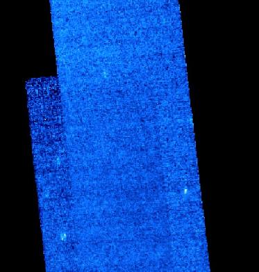
Figure 5: Mosaic of MIPS 326 24um scan map, showing the
uncommanded cross-scan offset of the first scan leg.
Examination of the expansion file produced by the AOR indicated that
the commanded cross-scan offset was indeed zero. However, a
visualization from SPOT conducted after FTU 9 was executed showed
the same offset! In fact, now there were offsets proportional
to the length of all scan leg AORs (with 80" as a minimal
value for fast scan).
Figure 6: MIPS 326 AOR visualized with SPOT 8.1 and FTU 9. Note
the cross-scan offset which did not appear in Figure 1.
The answer to this problem came after a
careful re-examination of the logic used to calculate the start
position of each scan map (thanks to Yi Mei, Terry Alt, and Lisa
Storrie-Lombardi). One output of the FPS process is an angle which
describes the "twist" of each array FOV with respect to the spacecraft
Y and Z axes. For the 70um WF FOV, the twist is nearly 3 degrees. Since
we lead with this FOV on forward scans and the AIRE coding uses
PCS_SET_VW to make the offset to the scan start position, the offset
occurs along the array V direction, not the spacecraft Y axis. This
introduces a cross-scan offset proportional to the length of the scan
leg. The reverse leg leads with the 160um frame, which has not been
updated to include its "twist angle"; thus, the reverse leg is centered
on the target at present. In order to circumvent this "feature" of
the AOT logic, we have created two new frames (113: MIPS_70um_scan;
114; MIPS_160um_scan) which will replace the frames set at the
beginning of each scan leg. These will replicate the array centers
of the previous frames, but set the twist angle = 0. Thus, we will
offset as expected at the beginning of each scan leg. This change
should be fully implemented prior to campaign P, when the scan map
AOT validation begins in earnest.
Here are the MIPS Enhancer mosaics produced with scale=0.25.
The 70um array data has been processed with flip_x. Note that
there is a periodic striping the in the Ge data which is
probably related to the stimflash cycle. The 160um data is
completely saturated in this low galactic latitude (3.1 deg!)
field. To see a sample mosaic for 160um and much good quick
look analysis, go to
Herve's page
Figure 7a: MIPS 326 24um scan map mosaic
|
Figure 7b: MIPS 326 70um scan map mosaic
|