There is a problem w/ your write-up. Check that you have valied entries for \$CAID and \$Campn in your analysis.php file. If that checks out, then Contact Stansberry"; return ; } // get first matching task $row = mysql_fetch_array($result); $title = $row["title"]; $princ = $row["principal"]; $deputy= $row["deputy"]; $campn0 = $row["campn0"]; $aorkeys = $row["aorkeys"]; // get real name of principal, deputies $princ = ioc_get_person($princ); $princ = $princ[0]; $deps = explode(",",$deputy); foreach ($deps as $depty) { $depty = trim($depty); $depty = ioc_get_person($depty); $depty = $depty[0]; $depty = explode(",",$depty); $depty = $depty[0]; // last names only $deplist[] = $depty; } $deplist = implode(", ", $deplist); $caid = sprintf("%03d",$caid); $file = "mips-".$caid.$campn.".analysis.php"; // if more matches, append the AORKEYS from those $numrows = mysql_num_rows($result); if ($numrows > 1) { $aorkeys = " " . $numrows . " Task Executions:  ". $aorkeys; for ($i=0;$i < mysql_num_rows($result); $i++) { $row = mysql_fetch_array($result); $morekeys = $row["aorkeys"]; $aorkeys = $aorkeys .';  '.$morekeys; } } // END PHP. ?> <? echo "MIPS-$caid, Campaign $campn IOC/SV Analysis"; ?>

Principal:
Deputy:
Analyst:
AORKEYS:
Last Updated:


Task Outcome Summary


Abstract

Validate that MIPS scan map AOT with medium scan rate is ready for the beginning of science operations.

Analysis

Data were obtained using the medium scan rate of MIPS scan map for the target M47, which is a young cluster with several stars visible in the optical/NIR and 24um bands. The following AOT parameters were used:
AORID
Leg Length (degrees)
# Legs
Cross-scan Offset (arcsec)
 FWD -> REV, REV->FWD

0007336192
1.5
1
0
0007336448
0.5
2
64
0007336704
0.5
2
148
0007336704
0.5
2
302
0007337216
1.0
6
276, 111
0007337472
6.0
2
217

Data were reduced using DAT v2.40 and 2.41. Centroids were determined for selected point sources using IDP3. Mosaics and distortion-corrected BCDs were created using MIPS_enhancer. Predicted CSMM offsets were obtained using the perl code developed by C. Engelbracht.
The important aspects of MIPS scan map which need to be verified prior to beginning of science operations include the following questions. Does the CSMM ramp rate match the spacecraft slew rate such that minimal image smear occurs at 24um? Does the predicted offset between DCEs match predictions to the degree that the 160um array produces a properly filled map? Does the image taken prior to stimflashes match the stimflash image spatially? Do the AORs produce the requested scan leg lengths, numbers of legs, and cross-scan offsets? Is the pointing reconstructed properly so that coadded images are not elongated? Can the SSC pipelines handle the very large data volumes implied by large scanmaps? Does the scan map mode produce scientifically valid data for all bands?

Results

PSF analysis for individual DCEs was done on 2MASS07361641-1445549 in AOR 0007336448. Figure 1 shows the PSF of this object for the forward and reverse scans.

caption1

caption1
Using IDP3, I applied a 2D Gaussian fit to the PSF of this object in DCEs 83 - 92 in the forward scan and DCEs 9-18 in the reverse scan. For forward scan, the PSF has a major axis of 2.16 +/- 0.03 and minor axis of 2.06 +/- 0.03 pixels. The PSF for reverse scan is very similar in size. Probably due to jitter, the position angle of the major axis varies somewhat with position. However, in the mean, the PA is consistent with slight elongation along the scan direction. Given an approximate pixel scale of 2.499 arcsec/pixel in x and 2.599 arcsec/pixel in y, this is equivalent to a PSF size of 5.20" in x and 5.67" in y. With MIPS Enhancer, I produced a subsampled, distortion corrected PSF from DCE 86 of the forward scan leg. This is shown in Figure 2.

The distortion-corrected PSF shows less evidence of enlongation, with FWHM of 5.4" x 5.3" oriented randomly. Thus, I conclude that the spacecraft rate is well matched to the rate of CSMM motion so that image motion compensation is achieved.
MIPS medium scan map is designed to produce a filled 160um map. It is supposed to do this by skipping alternately by 1 and 3 160um pixels. The current set of parameters for the telescope scan rate, CSMM, and Ge stimcycle are as follows: OMEGA (telescope scan rate in milliarcsec/sec) = 6520, STIMCYCLE (number of DCEs between stimflashes) = 25, RELPOS1 = 2048, RAMPSLOPE = 102, RELPOS2(forward scan) = 2289, RELPOS2(reverse scan) = 1807, STEPOFFSET(forward scan) = -19, STEPOFFSET(reverse scan) = 19. Time between DCEs is approximately 4.5 MIPS seconds (4.719 real seconds). The following table quantifies the expected CSMM DAC positions and offsets between consecutive DCEs expected for forward and reverse medium scans. Note that we are changing the OMEGA, RELPOS2, and STEPOFFSET for Campaign X3 and beyond. An update to this report will contain similar predicted moves for the new mirror parameters.
OMEGA (millarcsec/sec)/RAMPDIR
(0=FWD, 1=REV)
DCENUM
Time (real seconds)
Boresight Motion (arcsec)
Predicted SCANABS (coarse DAC)
CSMM Offset on sky (arcsec)
Offset from DCE0 (")
Offset from Prior DCE (")
Prior DCE Offset (+3% CSMM gain)
6520/0
0
0
0
2004.625
0
0
0
0
6520/0
1
4.725
30.807
2032.375
-14.786
16.021
16.021
15.577
6520/0
2
9.45
61.614
1999.875
2.531
64.145
48.124
48.64
6520/0
3
14.175
92.421
2027.625
-12.255
80.166
16.021
15.577
6520/0
4
18.9
123.228
1995.125
5.061
128.289
48.123
48.64
6250/0
5
23.625
154.035
2022.875
-9.723
144.312
16.023
15.58
6520/0
6
28.35
184.42
1990.375
7.592
192.434
48.122
48.64
6520/0
7
33.075
215.649
2018.125
-7.192
208.457
16.023
15.58
6520/0
8
37.8
246.456
1985.625
10.122
256.578
48.121
48.64
6520/0
9
42.525
277.263
2013.375
-4.662
272.601
16.023
15.58
6520/0
10
47.25
308.070
1980.875
12.653
320.723
48.122
48.64
6520/0
11
51.975
338.877
2008.625
-2.131
336.746
16.023
15.58
6520/0
12
56.7
369.684
1976.125
15.184
384.868
48.122
48.64
6520/0
13
61.425
400.491
2003.875
0.4
400.891
16.023
15.58
6520/0
14
66.15
431.298
1971.375
17.715
449.013
48.122
48.64
6520/0
15
70.875
462.105
1999.125
2.93
465.035
16.022
15.58
6520/0
16
75.6
492.912
1966.625
20.246
513.158
48.123
48.64
6520/0
17
80.325
523.719
1994.375
5.461
529.18
16.022
15.58
6520/0
18
85.05
554.526
1961.875
22.778
577.304
48.124
48.64
6520/0
19
89.775
585.333
1989.625
7.991
593.324
16.02
15.58
6520/0
20
94.5
616.140
1957.125
25.31
641.45
48.126
48.64
6520/0
21
99.225
646.947
1984.875
10.522
657.469
16.019
15.58
6520/0
22
103.95
677.754
1951.375
27.842
705.596
48.127
48.64
6520/0
23
108.675
708.561
1980.125
13.052
721.613
16.017
15.58
6520/0
24
113.4
739.368
1947.625
30.375
769.743
48.13
48.64
6520/0
25
118.125
770.175
2004.625
0
770.175
0.432
-0.479
6520/1
0
0
0
2009.375
0
0
0
0
6520/1 1
4.725
-30.807
1981.625
14.784
-16.023
-16.023
-15.58
6520/1
2
9.45
-61.614
2014.125
-2.531
-64.145
-48.122
-48.64
6520/1
3
14.175
-92.421
1986.375
12.253
-80.168
-16.023
-15.58
6520/1
4
18.9
-123.228
2018.875
-5.061
-128.289
-48.121
-48.64
6520/1
5
23.625
-154.035
1991.125
9.723
-144.312
-16.023
-15.58
6520/1
6
28.35
-184.842
2023.625
-7.592
-192.434
-48.121
-48.64
6520/1
7
33.075
-215.649
1995.875
7.192
-208.457
-16.023
-15.58
6520/1
8
37.8
-246.456
2028.375
-10.124
-256.58
-48.122
-48.64
6520/1
9
42.525
-277.263
2000.625
4.661
-272.602
-16.022
-15.58
6520/1
10
47.25
-308.070
2033.125
-12.655
-320.725
-48.123
-48.64
6520/1
11
51.975
-338.877
2005.375
2.131
-336.746
-16.021
-15.58
6520/1
12
56.7
-369.684
2037.875
-15.187
-384.871
-48.125
-48.64
6520/1
13
61.425
-400.491
2010.125
-0.4
-400.891
-16.02
-15.58
6520/1
14
66.15
-431.298
2042.625
-17.719
-449.017
-48.126
-48.64
6520/1
15
70.875
-462.105
2014.875
-2.93
-465.035
-16.018
-15.58
6520/1
16
75.6
-492.912
2047.375
-20.251
-513.163
-48.128
-48.64
6520/1
17
80.325
-523.719
2019.625
-5.461
-529.18
-16.017
-15.58
6520/1
18
85.05
-554.526
2052.125
-22.784
-577.31
-48.13
-48.64
6520/1
19
89.775
-585.333
2024.375
-7.992
-593.325
-16.015
-15.58
6520/1
20
94.5
-616.140
2056.875
-25.318
-641.458
-48.133
-48.64
6520/1
21
99.225
-646.947
2029.125
-10.523
-657.47
-16.012
-15.58
6520/1
22
103.95
-677.754
2061.625
-27.852
-705.606
-48.136
-48.65
6520/1
23
108.675
-708.561
2033.875
-13.055
-721.616
-16.01
-15.57
6520/1
24
113.4
-739.368
2066.375
-30.386
-769.754
-48.138
-48.66
6520/1
25
118.125
-770.175
2009.375
0
-770.175
-0.421
0.49

The table presumes that the direction of telescope motion is precisely along the scan mirror axis. Observed offsets between consecutive DCEs determined from centroiding on 2MASS 07361641-1445549 are listed in table 3. These offsets presume a fixed y pixel scale of 2.5993 arcsec/pixel.
FWD Scan Offset from Prior DCE (24um centroids, arcsec)
REV Scan Offset from Prior DCE (24um centroids, arcsec)
50.35
-14.89
15.35
-47.98
49.53
-15.1
15.46
-48.55
48.84
-15.31
15.21
-49.15
48.37
-15.46
15.08
-49.83
47.65
-15.47


With the current set of parameters for medium scan, a source appears in 9 or 10 consecutive DCEs (depending on the tolerance for proximity to the array edge). These observed offsets appear to indicate that the actual offsets between DCEs are within tenths of an arcsecond of the predicted offsets if a 3% increase in the CSMM gain (as observed in 24um photometry) is presumed. The SPOT visualization of medium scan shows tiny gaps in the 160um coverage which are less than 1" across. MIPS enhancer maps of the actual data appear to show the same effect. Since the observed offsets between DCEs are slightly less than 1 and slightly more than 3 times the advertised 160um sizes, we should expect to see some small gaps in the coverage. Further analysis is needed to establish the 160um pixel scale reliably and quantify the completeness in medium scan 160um maps.

Comparison of the 24um DCEs immediately before and during the Ge stimflash events shows minimal offset on the sky between these DCEs. For the forward scan DCE# 50 and 51, there is an offset of 0.88". For the reverse leg DCE# 50 and 51, there is an offset of 0.94". These are about 0.4" larger than the predicted offsets in Table 2. Another caveat for use is that there is no background field for the first stimflash in each scan leg. This will affect the first 25 DCEs (or 13 arcmin) in medium scan, making the Ge:Ga calibration less reliable. If we do not wish to change this design, we need to quantify the degredation in calibration for these DCEs and notify the users. (who might choose longer legs for mapping).

The next question is whether the medium scan AOT design properly implements user-selectable SPOT parameters such as length and number of scan legs and cross-scan offset between scan legs. Due to limited IOC time, these parameters were incompletely tested. We exercised the shortest and longest legs, as well as some intermediate values. Six of the 12 cross-scan offsets were tested. Finally, we performed six adjacent scan legs of 1 deg each, which took 7300 sec. To determine the sizes of scan legs, I constructed 24um mosaics and measured the total lengths using the distance tool in GAIA. The 0.5 degree long scans (0007336448, 0007336704, 0007336960) are approximately 56' in total length, with the region of 3 band overlap = 35'. The 1 degree scan legs are 1.58 deg in length (3 band overlap 1.34 deg). The 1.75 degree scan legs are 2.02 deg in length (3 band overlap 1.64 deg). Finally, the 6 degree scan legs are 6.1 deg in length (overlap region ~same). The requested cross-scan offsets (64", 148", 217", 276", 302") were executed as expected with the following caveat: the offsets from FWD to REV were ~15" larger and the offsets from REV to FWD were 15" smaller. This was due to the fact that the leading frames for FWD (70um_scan) and REV (160um_scan) have different theta-Y (cross-scan) centers. This issue has been resolved by a frame change which will be implemented in Campaign X1.

At the current time, mosaics constructed using SSC WCS keywords show a non-negligible amount of smearing along the scan direction. Using the WCS alignment coadd in IDP3, I constructed coadds of the 2MASS 07361641-1445549 PSF which were analyzed by 2D gaussian fitting. For forward scan, the major axis is 2.92 pixels, and the minor axis is 2.29 pixels aligned with the scan direction (7.6" x 5.7").

A similarly elongated PSF is produced by reverse scan. Analysis by F. Masci has revealed that this smearing (which is worst for fast scan) is due to a synchronization problem in pointing reconstruction. Upon further investigation, D. Frayer discovered that the SCLKTIME was being calculated improperly in TRANHEAD. This problem has been solved and will be deployed online in S9.0. Until then, offline pointing can be run by request in order to make mosaics with good PSFs. Careful users will notice that mosaic PSFs which fall in the region of overlap between legs are even more elongate than those from single scan legs. This is also an artifact of the TRANHEAD problem.

One problem which was revealed by this task was an inadequacy in the SSC 160um ensemble processing. For AORID 07337472, the 160um data never completed its BCD processing. This error was repeated in Campaign Q for the 6 degree slow scan in MIPS 328 and 3 degree x 12 leg fast scans in MIPS 317. Diagnosis is still in work. Another pipeline deficiency which sometimes occurs manifests itself as a failure to make mosaics due to "overlarge mosaic size". What The 24um data from 7336192 has this defect, which is apparently due to a glitch in the Boresight Pointing History File (BPHF). It can be found by looking for outliers in CRVAL1 and CRVAL2. In these cases, the affected DCE should be excluded from the mosaic.

Photometry in the medium scan map mode is relatively consistent at 24um. Using a conversion factor of 1.503E5 DN/s/Jy, I measured a flux of 0.1956 +/- 0.003 in 8 consecutive 24um DCEs in 0007336960 for IRAS 07345-1403. This demonstrates repeatability of 1.5% in images without distortion correction. Interestingly, the 25um IRAS flux for this source is 0.314 Jy, so the agreement with IRAS for this source (of unknown nature) is not good. Using a MIPS enhancer mosaic for leg 2 of this AOR (-s 1, -RR), I get 0.141 Jy for the same source. The source of this discrepancy may be lack of flux conservation in the mosaicker, WCS image smear, or a combination of the two effects. The measured RMS noise in the mosaic does appear to be lower by a factor consistent with the increase in exposure time, but users should beware of photometry from enhancer mosaics until this problem is diagnosed and solved. The quality of 70um and 160um photometry are still in work.

The enhancer mosaics produced by medium scan are generally good at 24um, and less good at 70 and 160um. Below are shown the 24um mosaics for 0007336448, 0007336704, 0007336960, 0007337216, and 0007337472.

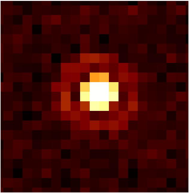
0007336448 0.5 deg scan, 64" offset

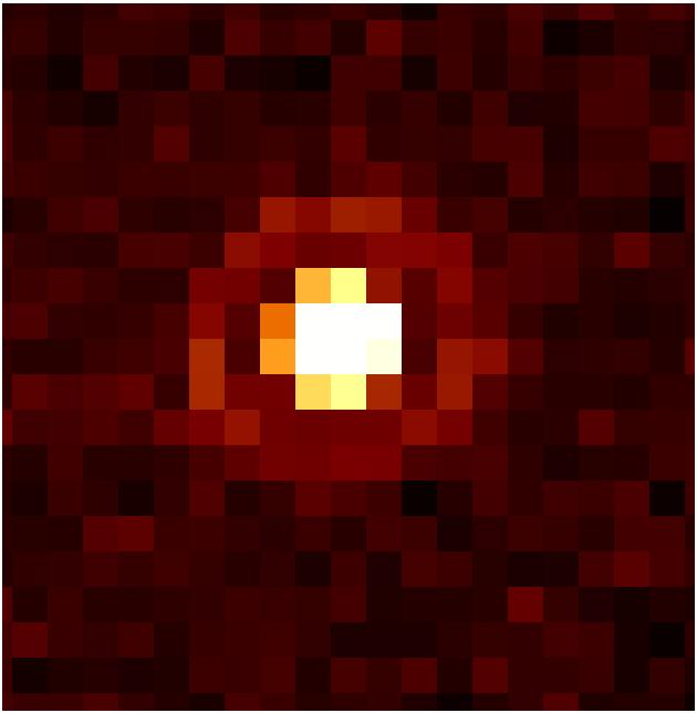
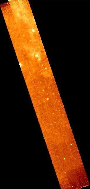
0007336704 0.5 deg scan, 148" offset

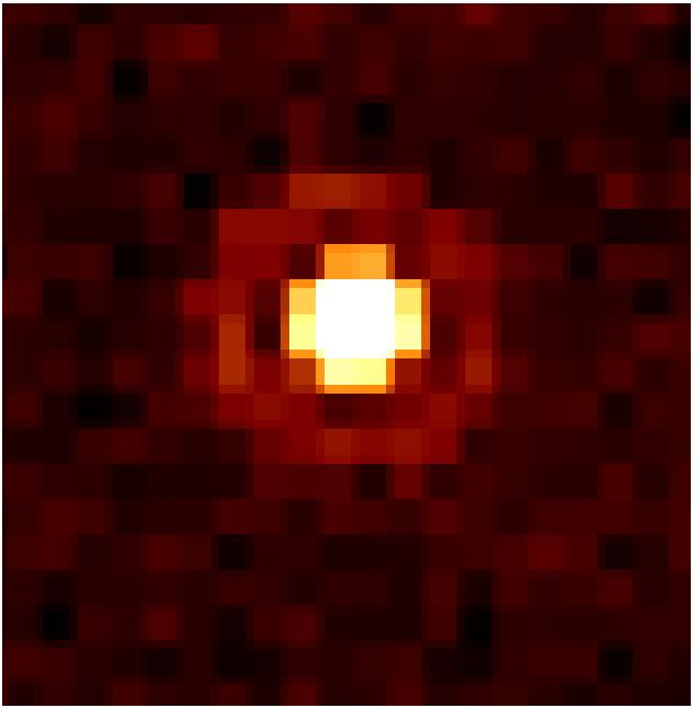
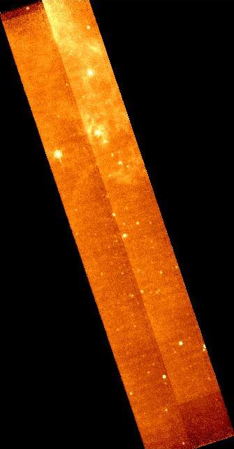
0007336960 0.5 deg scan, 302" offset

0007337216 1.0 deg scan, 276",111" offsets


0007337472 6 deg scan, 217" offset
Close examination reveals artifacts from the 24um "read2" effect, which produces low level horizontal stripes, and a cross-scan gradient within each scan leg. Preliminary investigation by J. Muzerolle finds that using a flat produced by scan rather than photometry eliminates this gradient, which is the major source of the seams in the mosaic. Low level dark streaks from the POM contamination are also present. The 6 deg legs from 0007337472 also show a 40 DN/s decrease in the background from the north to south end. This effect is shown consistently in multiple scan legs and is most likely due to the change in ecliptic latitude along the scan. On the other hand, the 70um mosaics are relatively poor in quality. The following figure depicts a 70um mosaic for one leg of 0007336448. The image is dominated by dark stripes along the scan direction and stimflash latents. Only a few point sources are apparent along the 0.5 degree strip and the extended emission in the region does not appear at all. The 160um mosaic for the same AOR at least shows extended emission in the same regions that 24um does. There are also somewhat less obvious dark stripes in the 160um map, suggesting that scan mirror angle dependent ICs may be necessary in this band as well.

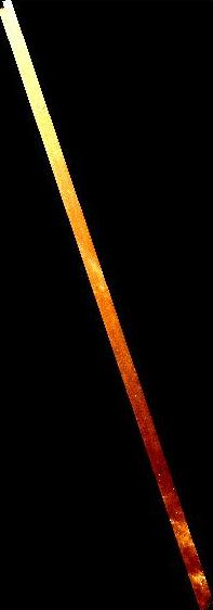
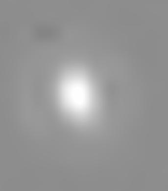
0007336448 70um Leg 1

0007336448 160um

Comparisons with the SSC MOPEX mosaicker will be added later.

Conclusions

MIPS medium scan mapping appears to produce good 24um images for the CSMM and spacecraft parameters input at the beginning of IOC. The image quality will be reassessed in Campaign X3 with a new set of IPP parameters. Given that the CSMM gain is slightly different from prelaunch predictions, the offset from DCE to DCE is close to expectations. A TRANHEAD error in the current online SSC pipeline causes image smearing in the mosaics. This will be fixed in the S9.0 pipeline deployed in December. Image quality at 70um is relatively poor, and scan mirror dependent IC (+ possibly high-pass filtering) is needed to recover better performance in this band.

Output and Deliverable Products

None

Actions Following Analysis

Fixes to FOV table (done) + pipelines.