There is a problem w/ your write-up. Check that you have valied entries for \$CAID and \$Campn in your analysis.php file. If that checks out, then Contact Stansberry"; return ; } // get first matching task $row = mysql_fetch_array($result); $title = $row["title"]; $princ = $row["principal"]; $deputy= $row["deputy"]; $campn0 = $row["campn0"]; $aorkeys = $row["aorkeys"]; // get real name of principal, deputies $princ = ioc_get_person($princ); $princ = $princ[0]; $deps = explode(",",$deputy); foreach ($deps as $depty) { $depty = trim($depty); $depty = ioc_get_person($depty); $depty = $depty[0]; $depty = explode(",",$depty); $depty = $depty[0]; // last names only $deplist[] = $depty; } $deplist = implode(", ", $deplist); $caid = sprintf("%03d",$caid); $file = "mips-".$caid.$campn.".analysis.php"; // if more matches, append the AORKEYS from those $numrows = mysql_num_rows($result); if ($numrows > 1) { $aorkeys = " " . $numrows . " Task Executions:  ". $aorkeys; for ($i=0;$i < mysql_num_rows($result); $i++) { $row = mysql_fetch_array($result); $morekeys = $row["aorkeys"]; $aorkeys = $aorkeys .';  '.$morekeys; } } // END PHP. ?> <? echo "MIPS-$caid, Campaign $campn IOC/SV Analysis"; ?>

Principal:
Deputy:
Analyst:
AORKEYS:
Last Updated:


Task Outcome Summary


Abstract

Validate that MIPS scan map AOT with slow scan rate is ready for the beginning of science operations.

Analysis

Data were obtained using the medium scan rate of MIPS scan map for the target M47, which is a young cluster with several stars visible in the optical/NIR and 24um bands. The following AOT parameters were used:
AORID
Leg Length (degrees)
# Legs
Cross-scan Offset (arcsec)
 FWD -> REV, REV->FWD

0007427072
1.5
1
0
0007427328
0.5
2
35
0007427584
0.5
2
148 (map center offset -3600")
0007427840
0.5
2
302
0007428096
6.0
1
0
0007428352
0.5
5
276,111
0008149614
0.5
2
0

Data were reduced using DAT v2.42 and 2.50. Centroids were determined for selected point sources using IDP3. Mosaics and distortion-corrected BCDs were created using MIPS_enhancer. Predicted CSMM offsets were obtained using the perl code developed by C. Engelbracht (version updated 12/3/03).
The important aspects of MIPS scan map which need to be verified prior to beginning of science operations include the following questions. Does the CSMM ramp rate match the spacecraft slew rate such that minimal image smear occurs at 24um? Does the predicted offset between DCEs match predictions to the degree that the 160um array produces a properly filled map? Does the image taken prior to stimflashes match the stimflash image spatially? Do the AORs produce the requested scan leg lengths, numbers of legs, and cross-scan offsets? Is the pointing reconstructed properly so that coadded images are not elongated? Can the SSC pipelines handle the very large data volumes implied by large scanmaps? Does the scan map mode produce scientifically valid data for all bands?

Results

PSF analysis for individual DCEs was done on 2MASS07360829-1441528 in AOR 0008149504. Figure 1 shows the PSF of this object for the forward and reverse scans.

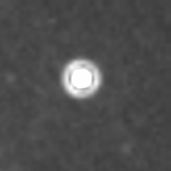
PSF for FWD Slow scan

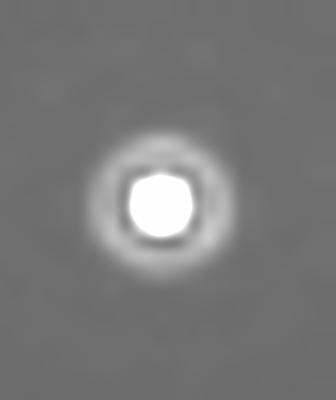
PSF for REV Slow scan
Using IDP3, I applied a 2D Gaussian fit to the PSF of this object in DCEs 84 - 92 in the forward scan and DCEs 17-25 in the reverse scan. For forward scan, the PSF has a major axis of 2.18 +/- 0.03 and minor axis of 2.12 +/- 0.03 pixels. The PSF for reverse scan is very similar in size. Probably due to jitter, the position angle of the major axis varies somewhat with position. However, in the mean, the PA is consistent with slight elongation along the scan direction. Given an approximate pixel scale of 2.499 arcsec/pixel in x and 2.599 arcsec/pixel in y, this is equivalent to a PSF size of 5.44" in x and 5.67" in y. Thus, I conclude that the spacecraft rate is well matched to the rate of CSMM motion so that image motion compensation is achieved.
MIPS slow scan map is designed to produce a filled 160um map. It is supposed to do this by skipping alternately by 1 and 3 160um pixels. The current set of parameters for the telescope scan rate, CSMM, and Ge stimcycle are as follows: OMEGA (telescope scan rate in milliarcsec/sec) = 2580, STIMCYCLE (number of DCEs between stimflashes) = 11, RELPOS1 = 2048, RAMPSLOPE = 257, RELPOS2(forward scan) = 2273, RELPOS2(reverse scan) = 1823, STEPOFFSET(forward scan) = -41, STEPOFFSET(reverse scan) = 41. Time between DCEs is approximately 10.5 MIPS seconds (11.025 real seconds). The following table quantifies the expected CSMM DAC positions and offsets between consecutive DCEs expected for forward and reverse medium scans.
OMEGA (millarcsec/sec)/RAMPDIR
(0=FWD, 1=REV)
DCENUM
Time (real seconds)
Boresight Motion (arcsec)
Predicted SCANABS (coarse DAC)
CSMM Offset on sky (arcsec)
Offset from DCE0 (")
Offset from Prior DCE (")
2580/0
0
0
0
2001.88
0
0
0
2580/0
1
11.025
28.444
2024.88
-12.812
15.632
15.633
2580/0
2
22.05
56.889
1991.62
5.709
62.598
46.966
2580/0
3
33.075
85.333
2014.62
-7.102
78.231
15.634
2580/0
4
44.1
113.778
1995.125
11.419
125.197
46.966
2580/0
5
55.125
142.222
2014.62
-1.392
140.831
15.634
2580/0
6
66.15
170.667
1971.12
17.129
187.796
46.966
2580/0
7
77.125
199.111
1994.12
4.317
203.429
15.633
2580/0
8
88.2
227.556
1960.88
22.84
250.396
46.967
2580/0
9
99.225
256.000
1983.88
10.026
266.026
15.631
2580/0
10
110.25
284.445
1950.62
28.553
312.890
46.972
2580/0
11
21.275
312.889
2001.88
0 312.890
-0.109
2580/1
0
0
0
2012.12
0
0
0
2580/1 1
-11.025
-24.444
1989.12
12.811
-15.634
-15.634
2580/1
2
-22.05
-56.889
2022.38
-5.71
-62.599
-46.966
2580/1
3
-33.075
-85.333
1999.38
7.102
-78.231
-15.633
2580/1
4
-44.1
-113.778
2032.62
-11.42
-125.198
-46.966
2580/1
5
-55.125
-142.222
2009.62
1.393
-140.830
-15.632
2580/1
6
-66.15
-170.667
2042.99
-17.133
-187.8
-46.971
2580/1
7
-77.175
-199.111
2019.99
-4.317
-203.429
-15.629
2580/1
8
-88.2
-227.556
2053.12
-22.847
-250.403
-46.974
2580/1
9
-99.225
-256.000
2030.12
-10.027
-266.023
-15.625
2580/1
10
-110.25
-284.445
2063.38
-28.563
-313.008
-46.981
2580/1
11
-121.275
-312.889
2012.12
0
-312.889
0.119

The table presumes that the direction of telescope motion is precisely along the scan mirror axis. Observed offsets between consecutive DCEs determined from centroiding on 2MASS 07360829-1441528 are listed in table 3. These offsets presume a fixed y pixel scale of 2.5993 arcsec/pixel.
FWD Scan Offset from Prior DCE (24um centroids, arcsec)
REV Scan Offset from Prior DCE (24um centroids, arcsec)
15.85
-46.03
47.53
-15.44
15.70
-46.63
46.98
-15.65
0.158 -47.16
15.56
-0.096
46.44 -15.64
15.40
-47.74


With the current set of parameters for slow scan, a source appears in 9 or 10 consecutive DCEs (depending on the tolerance for proximity to the array edge). These observed offsets appear to indicate that the actual offsets between DCEs are within a few tenths of an arcsecond of the predicted offsets. MIPS enhancer maps of 8149504 appear to show no gaps in the 160um coverage other than for the bad readout.

Comparison of the 24um DCEs immediately before and during the Ge stimflash events shows minimal offset on the sky between these DCEs. For the forward scan DCE# 87 and 88, there is an offset of 0.24". For the reverse leg DCE# 21 and 22, there is an offset of -0.19". These are about 0.1" larger than the predicted offsets in Table 2.

The next question is whether the slow scan AOT design properly implements user-selectable SPOT parameters such as length and number of scan legs and cross-scan offset between scan legs. Due to limited IOC time, these parameters were incompletely tested. In addition, this testing was done using
CSMM parameters and slew speeds which are no longer in use. We exercised the shortest and longest legs, as well as some intermediate values. Six of the 12 cross-scan offsets were tested. Finally, we performed 5 adjacent scan legs of 0.5 deg each, which took 7300 sec. To determine the sizes of scan legs, I constructed 24um mosaics and measured the total lengths using the distance tool in GAIA. The 0.5 degree long scans (0007427328, 0007427540, 0007427840, and 0007428352) are approximately 56' in total length, with the region of 3 band overlap = 35'. The 1.5 degree scan leg is 1.95 deg in length (3 band overlap 1.64 deg). Finally, the 6 degree scan legs are 6.5 deg in length (overlap region ~same). The requested cross-scan offsets (64", 148", 217", 276", 302") were executed as expected with the following caveat: the offsets from FWD to REV were ~15" larger and the offsets from REV to FWD were 15" smaller. This was due to the fact that the leading frames for FWD (70um_scan) and REV (160um_scan) have different theta-Y (cross-scan) centers. This issue has been resolved by a frame change which was be implemented in Campaign X1.

As of S8.9 at the SSC, mosaics constructed using SSC WCS keywords show a small amount of smearing along the scan direction for slow scan only. Using the WCS alignment coadd in IDP3, I constructed coadds of the 2MASS 07360829-1441528 PSF which were analyzed by 2D gaussian fitting. For forward scan, the major axis is 2.34 pixels, and the minor axis is 2.29 pixels aligned with the scan direction.

A similarly elongated PSF is produced by reverse scan. Analysis by F. Masci has revealed that this smearing (which is worst for fast scan) is due to a synchronization problem in pointing reconstruction. Upon further investigation, D. Frayer discovered that the SCLKTIME was being calculated improperly in TRANHEAD. This problem has been solved and has been deployed online in S9.0. Until then, offline pointing can be run by request in order to make mosaics with good PSFs. Careful users will notice that mosaic PSFs which fall in the region of overlap between legs are even more elongate than those from single scan legs. This is a different effect which involves a synchronization problem between scan legs. For slow scan, it produces the effect of a PSF with major axis 3.127 pixels and minor axis 2.571 pixels aligned along the scan direction. It has been repaired with an ad hoc DC offset to the relative timing between scan legs in S9.0. However, a real diagnosis of the problem has yet to be made.

One problem which was revealed by this task was an inadequacy in the SSC 160um ensemble processing. For AORID 0007428096, the 160um data never completed its BCD processing. This error was repeated in Campaign P for the 6 degree medium scans in MIPS 327 and 3 degree x 12 leg fast scans in MIPS 317. Diagnosis is still in work.

Photometry in the slow scan map mode is relatively consistent at 24um. Using a conversion factor of 1.50E5 DN/s/Jy, I measured a flux of 0.0507 +/- 0.001 Jy in 8 consecutive FWD scan 24um DCEs in 0008149504 for 2MASS 07360829-1441528. This demonstrates repeatability of 2.3% in images without distortion correction. The photometry for the reverse scan is a bit different. Using the same conversion factor as for FWD scan, I get a flux of 0.052 +/- 0.002 Jy. Using a MIPS enhancer mosaic for leg 1 of this AOR, I get 44 mJy for the same source. The source of this discrepancy is probably lack of flux conservation in the mosaicker for "-s 1". The measured RMS noise in the mosaic does appear to be lower by a factor consistent with the increase in exposure time, but users should beware of photometry from enhancer mosaics until this problem is diagnosed and solved. The quality of 70um and 160um photometry are still in work.

The enhancer mosaics produced by medium scan are generally good at 24um, and less good at 70 and 160um. Below is shown a 24um mosaic which combines data from 0007427072, 0007427328, 0007427584, and 0007428352.

Combination mosaic of 24um slow scans, M47

Conclusions

MIPS slow scan mapping appears to produce good 24um images for the CSMM and spacecraft parameters input at the beginning and end of IOC. Given that the CSMM gain is slightly different from prelaunch predictions, the offset from DCE to DCE is close to expectations. A TRANHEAD error in the current online SSC pipeline causes image smearing in the mosaics. This was fixed in the S9.0 pipeline deployed in December. Image quality at 70um is relatively poor, and scan mirror dependent IC (and/or possibly high-pass filtering) is needed to recover better performance in this band.

Output and Deliverable Products

None

Actions Following Analysis

Fixes to FOV table (done) + pipelines (in work). Fixes to FOV table (done) + pipelines.